This website uses cookies to enhance usability and provide you with a more personal experience. By using this website, you agree to our use of cookies as explained in our Privacy Policy.
Preparing project drawings can be a new process for many applicants. The information below outlines our drawing standards and requirements to help you create clear, complete plans and submit a successful permit application.
A site plan is an aerial view of a property that shows all existing and proposed improvements to the site. It is required as part of your permit application.
Preparing a site plan
A site plan can be prepared by an architect, draftsperson using design software, or can be hand drawn for permits related to decks, garages, and accessory structures.
If drawing by hand, the following are a few pointers to ensure that your drawing is clear and acceptable as a part of your application:
Ensure labels and measurements are clearly printed.
Use ink when drawing the plan to improve legibility when it is scanned.
Standard information in a site plan
Including the following information in your site and floor plans help us better understand and interpret the plan.
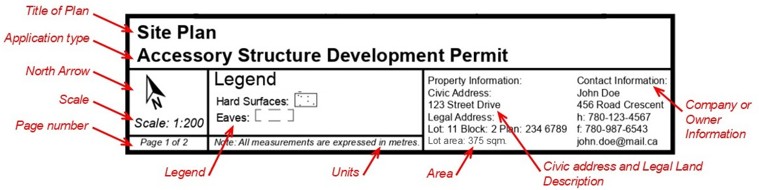
Title of the plan (e.g., Site Plan or Floor Plan).
Application type: The type of development being applied for (e.g., Accessory Structure Development Permit),
Civic address of the property.
Legal land description of the property (Lot/Block/Plan). The Civic Address Translator can help you find your legal land description.
Company or owner information, including your name, address, telephone numbers, e-mail address, and fax number.
North arrow showing the orientation of your property to north.
Area: Site plans should include the lot area, and floor plans should include the floor area.
Units of measurement used in the plan. Metric units are accepted.
Scale of the drawing. This can be indicated using a scale bar or a ratio (e.g., 1:50 or 1:100).
A legend should identify and describe all the symbols used in the plan.
Page numbers: Properly number all the plans submitted as part of a package of plans. For example, if a site plan and a floor plan are being submitted, they should be numbered 1 of 2 and 2 of 2.
All of this information should be presented in a title block. See the example below:
Checklist for a site plan
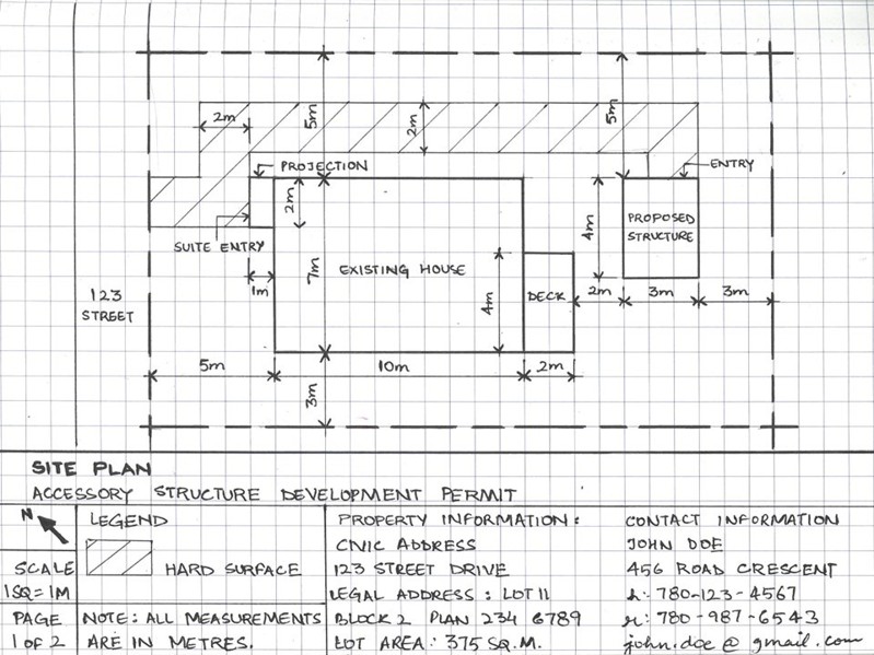
Site plans are used to show where things are located, their size, and how far they are from other things on the property. In addition to including standard information, the following information is required in the site plan for a successful application:
Property lines.
Lot dimensions.
Draw and label the streets and/or roads abutting the property.
Size and location of the relevant existing structures or buildings on the site.
Size and location of all the proposed structures or changes.
Properly label all the proposed and existing structures.
Indicate entrances to the structures.
Setbacks: Show how far the structures are from the property lines.
Distances between all the structures on the property.
Size and location of any hard surfaces on the property, such as driveways or walkways.
Size and location of any easement on the property, if applicable.
Size and location of any eaves or roof overhangs for both existing and proposed structures, if applicable.
Lot grades for new constructions of single detached dwellings.
Sample site plan
Floor plan guide
A floor plan is an aerial view of the floor of a building. It shows the dimensions of exterior walls, the layout, use and dimensions of interior spaces, and the location and dimensions of windows and doors.
Preparing a floor plan
A floor plan can be prepared by an architect, draftsperson using design software, or can be hand drawn for permits related to single detached houses, accessory structures, and secondary suites.
If drawing by hand, the following are a few pointers to ensure that your drawing is clear and acceptable as a part of your application:
Ensure labels and measurements are clearly printed.
Use ink when drawing the plan to improve legibility when it is scanned.
Standard information in a site plan
Including the following information in your site and floor plans help us better understand and interpret the plan.
Title of the plan (e.g., Site Plan or Floor Plan).
Application type: The type of development being applied for (e.g., Accessory Structure Development Permit),
Civic address of the property.
Legal land description of the property (Lot/Block/Plan). The Civic Address Translator can help you find your legal land description.
Company or owner information, including your name, address, telephone numbers, e-mail address, and fax number.
North arrow showing the orientation of your property to north.
Area: Site plans should include the lot area, and floor plans should include the floor area.
Units of measurement used in the plan. Metric units are accepted.
Scale of the drawing. This can be indicated using a scale bar or a ratio (e.g., 1:50 or 1:100).
A legend should identify and describe all the symbols used in the plan.
Page numbers: Properly number all the plans submitted as part of a package of plans. For example, if a site plan and a floor plan are being submitted, they should be numbered 1 of 2 and 2 of 2.
All of this information should be presented in a title block. See the example below:
Checklist for a floor plan
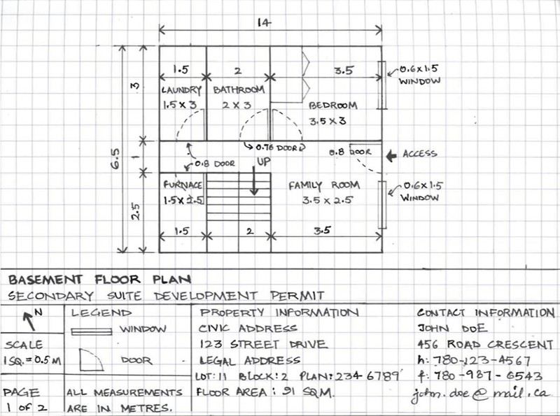
Floor plans are used to show the location and sizes of spaces, walls, stairways, and openings. In addition to including standard information, the following information is required in your floor plan for a successful application:
Dimensions of exterior walls.
Label and provide dimensions for all interior spaces (e.g., bedrooms, kitchen, laundry room, etc.).
Size and location of any decks or projections, if applicable.
Location of doors and windows. Additionally, indicate the sizes of doors and windows for a basement plan.
Size and location of window wells, wherever applicable.
Indicate independent and direct access from the outside to the basement or suite.
Indicate the location of the stairway with stairway direction, if applicable.
Sample floor plan
Drawing a plan to scale
Drawing scales are expressed as a ratio, which describes the relationship between the drawing’s dimensions and the actual object’s dimensions.
A scaled drawing depicts how big or small an object is compared to real life (scale of 1:1). For instance, a figure at a scale of 1:200 means that it is 200 times smaller than it is in real life. This means that one unit on the drawing is equal to 200 units in the real world.
Note: In a scale, the first number will always be 1, but the second number (also called the scale factor) will change to reflect the scale being used, which is typically a whole number and multiple of 5.
Drawing to scale
There are multiple methods that can be used to draw a plan to scale. Two of these methods are described below.
This method involves converting real life dimensions by dividing them with the scale factor to get the scaled drawing measurements.
Scaled dimensions = Real life dimensions ÷ Scale factor
Example: We are drawing a bed that measures 150cm x 200cm at a scale of 1:25. This means that 1 unit on drawing represents 25 units in the real world.
So, on paper, you would draw the bed 6cm x 8cm. This size is calculated by dividing the real size of the bed (150cm) by our chosen scale factor (25 in this case), which results in a width of 6cm. Similarly, the length is calculated by dividing 200cm by 25, resulting in 8cm.
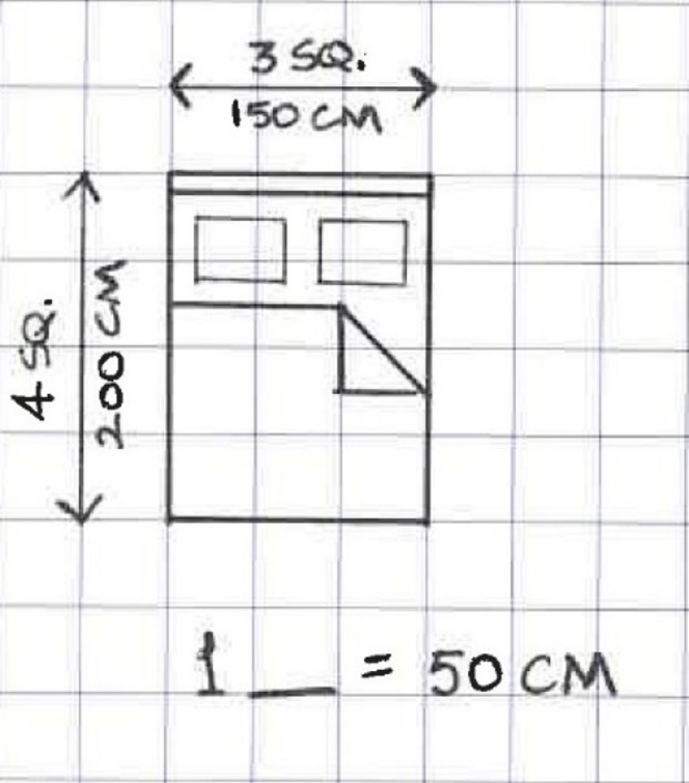
This method involves drawing figures or plans on a graph paper. Each square of the graph paper represents a unit of measurement of our choice.
Example:
Let’s draw the 150cm x 200cm bed on graph paper. Each side of the square represents 50 cm. As a result, the width of the bed (150cm) would be represented by 3 squares, and the length (200cm) by 4 squares.